EMERGENCY TOWER EVACUATION
September 17 th 2001
To get in touch with the author :
Jean-Pierre Petit, Astrophysicist,
France
Translated by Benjamin Rottier
We've all seen how vulnerable skyscrapers are, as were the Twin towers, Manhattan's pride, assembly of iron and concrete.
Remark, 2008/1/30. I wrote these sentences on 2001/9/17. : When the terrorists crashed their aircrafts on the towers, they had chosen planes crammed whith fuel, knowing its ignition would make the towers collapse. Without this use of heat, towers would have been seriously damaged but would have stood up. This successive floors' collapse phenomenon is inevitable. If such an event had to happen again, buildings' occupants should be able to evacuate it in a very short time, before the heat could have its disastrous effects.
It shows how we believed immediatly in the official thesis. Things have change now.
After fire in San Francisco, Americans, traumatized by its
effects, had made outside staircases general. But this solution could not be
applied to very tall buildings. We suggest another one here, to be examined.
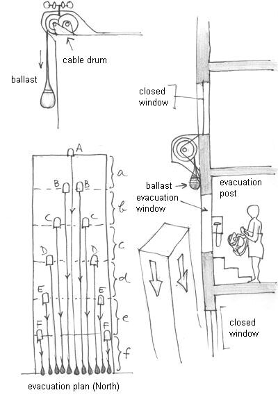
Below, the general tower evacuation plan, that takes place outside, along cables. Those cables are fixed on drums starting at various floors depending on the people to be evacuated. Thus the central A cable would be assigned to the rescue of a floors residents living on that side of the building. Up left, the unwinding system. The drum is unlocked by triggering the mechanism from inside, near the corresponding evacuation post. The cable will be pulled downwards by a profiled ballast (in order it not to cling to a façade's relief), speed being limited by an aerodynamic brake.
As noticed Alexandre Berube, Canadian engineer, more cables would be needed for the upper floors. With all due respect to my Canadian friend Norman, the use of standard abseiling devices and ascent ropes is not possible. Indeed, you have to make the rope zigzag to put the abseiling device on. That's impossible if the rope is tightened by several persons still descending below.
The 'socks' evacuation system has been mentioned. It's very clever. Long nylon tubes are unfurled on the façade. People go into through the upper neck. Nobody can die of suffocation because of their permeability. It's impossible to stop the descent, because there is no relief inside; this prevents lifeless bodies from being trapped too. The speed is limited by the rubbing of clothes on the tube's inner surface. It's nearly the same for everyone, whatever the height or the corpulence. Indeed, Norman said, a big person will have a larger contact surface with the tube. The vertical speed is about 2 m/s. As the tubes don't reach the ground, the evacuation is automatic. Of course, people can enter the tube in only one point, but increasing the number of tubes would resolve this problem. Those devices are moreover quite cheap and can be produced in great numbers. The only drawback: if people are dressed with short-sleeved shirts or shorts and if the building is tall, the friction on the skin could cause some burns. But suffering from slight burns is better than being buried under iron and concrete rubble, isn't it?
A remark: are buildings located in high risk seismic areas provided with such evacuation systems? Just remember several things. When an earthquake occurs and if the building does not collapse, its distorsion jams systematically every doors in their frames and it's absolutely impossible to open them. You will have to break it down, if you're able to. Moreover, as in case of fire, stairwells are the first structures to be damaged. Remember too that there often are successives tremors. How many people would have been saved, even in few floors buildings, if they had could evacuate it from the first heralding signs?
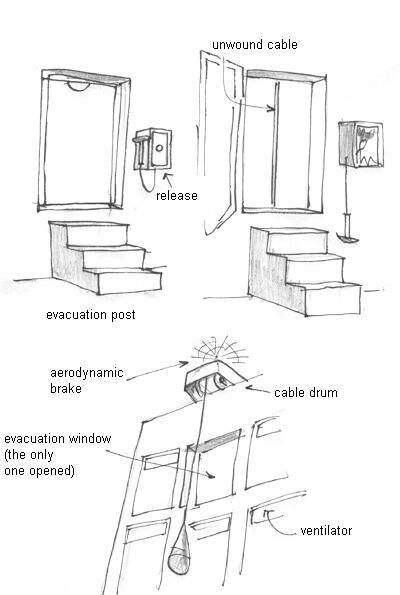
On the following drawing, an inside view of the evacuation post. Only those windows can be opened completely and lead to a small platform, on which a few people can stand up without risking to slip. Stairs allow to reach quickly the evacuation plateform. You can see the cable uncoiled (diameter: about 5 mm). Below: the cable unwinding and view on the rotating aerodynamic brake.
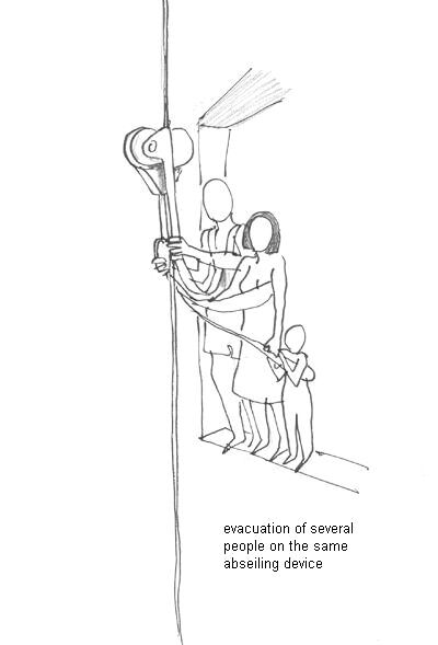
On the drawing below, a group of people (a couple with a child) about to drop. Each one's equipment will be detailed afterwards.
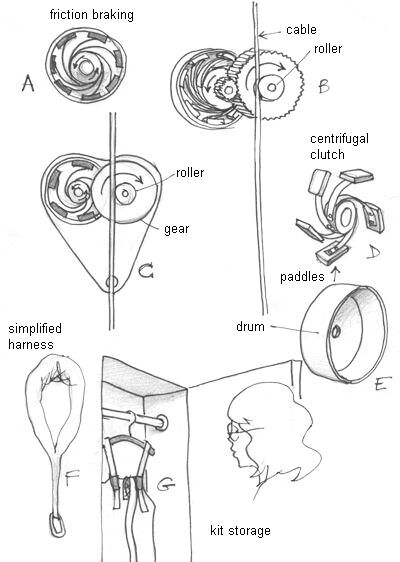
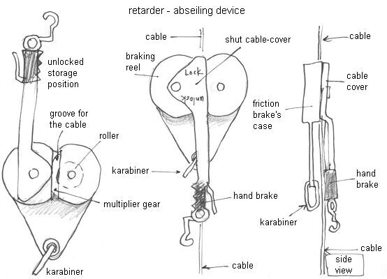
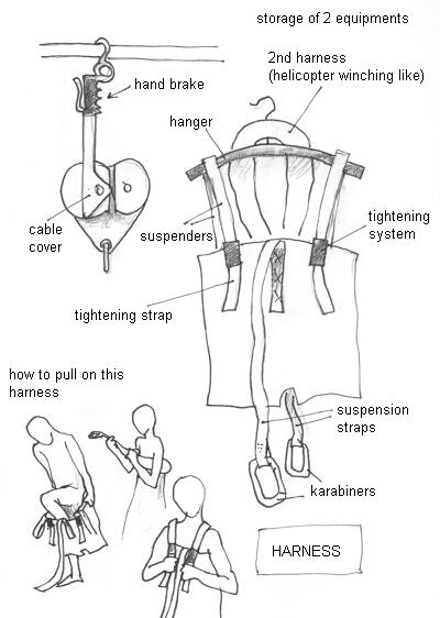
Below, the basis of the mechanism. It is a descent retarder, working on friction. In A, the flexible paddles system, stemmed from cars' centrifugal clutches, in its case. The paddles system is shown out of its case in D. The flexible steel paddles are linked to elements that rub on the inside part of the E drum. In B, you can see the cable rubbing on one of the rollers, interdependent with a gear increasing the rotation. In C, a schematic drawing: on the right, the roller and the gear; on the left, the braking paddles rotating in their race. In G, a storage cupboard for two equipments, being different by the way they're coupled with the descent retarder. On the left, a simplified harness (similar to harnesses used to winch up somebody from a helicopter).
Following drawings: the complete descent retarder. The paddles working on friction are not visible anymore. They're shut in their case. A image: the 'cable-cover' is upwards, in unlocked position. The device is stored in a cupboard in that configuration, hung by the suspension hook. Below, a plate interdependent with the two cases (the second one containing the increasing gear, interdependant with the rubber roller you can see a part of, black-colored). The plate is equipped with a karabiner for people to hang. The system has a groove in which the cable is put. The cable is strongly tightened by the heavy ballast that brought it down to the ground, it is linked to by a tension spring (to prevent cables from being moved by wind). The cable then has to be shut in the groove by turning the cable-cover and the hand braking handle of 180°. B drawing: system ready for the descent. The triangular-shaped cable-cover, hides the groove in which the cable has been inserted. Doing this, the cable is pressed against the first rubber roller. The hand braking control handle is downwards. In C, a side view of the device.
Following drawing: the storage. A: the descent retarder hanging, hand brake upwards, in the unlocked position. You can see the groove in which the cable runs. In B, a nylon harness looking like pants so that lifeless persons or people likely to panic could be evacuated. Being winched up from a helicopter or dropping from a height of 400 meters may not make you feel the same impressions. Elderly people, persons with impaired mobility or children shall not be forgotten. In C, someone pulling on the pants-harness. In D, he tightens the suspenders. Near him, a people equipped with a simplified harness (winching like). The suspension is carried out by a sewn nylon strap, ended with a karabiner.
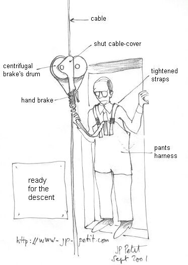
Below, a man ready to jump. His descent retarder has been positioned. The cable-cover is shut, securing by the same token the contact of the cable with the rollers. He has tightened his suspenders and is fastened to the retarder. He holds his suspenstion strap in his right hand and is about to grap the hand brake in his left one. None of those holds are essential to safety, the device being able to put the load down to the ground automatically.
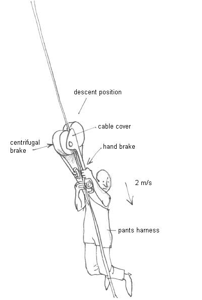
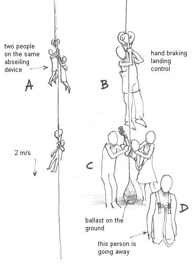
On this bird's eye view, someone descending. His left hand is on the hand brake, he will use in theory only near the ground to avoid hitting a person having already reached his destination but who has not yet gone away or been removed. A "normal weight" person could descent at about 2 m/s. The rubbing being proportional to the square of the descent's speed, this one would not increase so much if several people were hanging to the same retarder or if people were more heavy. When I jumped with age-old hemispherical parachutes, the usual vertical speed at the time of the impact was 6 m/s.
Next view: several people on the same abseiling device. Anyway, a person in charge of the evacuation post would stand at each platform. He would fix the descent retarder to the cable and the karabiner to people coming. He would show them the hand brake handle, remind them of its use and would check that everything is OK before allowing the jump.
Lastly, people should be received. In order the evacuation to be as quick as possible, people would be spaced by only few feet on a same cable. The onus is on them to control their descent speed, thanks to the hand brake, and to keep their distance with the person below, without ever reducing the vertical influx. Two people would play a major role in the evacuation operations (there should be a periodical training): the first one would use the cable to wait on the ground for the 'loads'. He would swiftly take off the abseiling devices, turning up the cable-cover and so allowing the cable to go out of the groove. Above, someone has used his hand brake and is waiting, in order not to disrupt the operation (B). On the foreground, someone going away quickly (D).
If such a system had been installed on each of the four sides of the towers in New York, thousands of human lives might have been saved. But who could have foreseen such a horror?
Today, we do know.
September, 17th 2001
The cables' unwinding remains problemactic, above all from several hundred metres, because of the effect of crosswind. Cables mustn't be tangled by the effect of a gust of wind, or people would hit each other. We had simply envisaged a heavy ballast. But no ballast would be able to tighten the cable if it is two, three or even four hundred metres long. The solution would so be to lock the cable down below. In order to do that, ballasts could be profiled as shells (B) and drop (A) quite quickly (minimal aerodynamic braking) towards shafts blocked up with plastic manhole covers, strong enough to withstand a man's weight but fragile enough to explode at the time of the impact. Shells would centre in cone-shaped guides. The locking could be automatic.
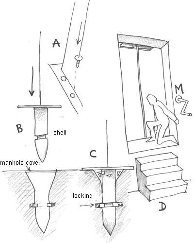
In D, the person who has triggered the drop of the cable could tighten it with a simple handle (M). If, as written above, cables were assigned to the evacuation of a finite number of floors, the unwinding of the cable and its tightening could be done from several operating and evacation posts (if only because one of them may be inaccessible).
We here talked about a friction retarder, stemmed from cars' clutches. A system stemmed from the classic James Watt's fly-ball governor might ensure a constant descent speed, whatever the load is (because this system has a very 'unlinear' response).
Fly-ball governor
In these conditions, the hand brakes could be removed and that would probably be better. Indeed, there would be a risk that someone panicking or becoming dizzy clenches his hand on the brake, blocking all the evacuation chain. If people can go down at very similar speeds, spacing out the jumps from the plateform would ensure for the man on the ground enough time to free people arriving.
Everything above is only ideas I've jotted
down as they came. But they seem to show that without changing current buildings,
they can be provided with an efficient evacuation system. No one had foreseen
the effects of such terrorist attacks on the buildings' structure. No fireman,
no architect, no specialist in security could have thought that the structure
could be attacked in a very short time because of the provision of thousands
liters of kerosene softening the reinforcing steel rods, then causing the floors'
collapse like dominoes. In the future, even the most incredible ideas should
be taken into consideration.
One more word :
This text won't be followed by any patent registration. I believe some things are more urgent than trying to make money with the security business. Above all, human lives have to be saved. Thus, those ideas are totally free for anyone wanting to apply them. When your house is burning, you don't waste time cleaning the livingroom.
From 2001, november tyhe 15 th, number of connexions :
![]()